Checking of absolute elevations |


|
|
This task is intended for the checking of absolute elevations of objects and depths values of isobaths of a vector map's sheet.
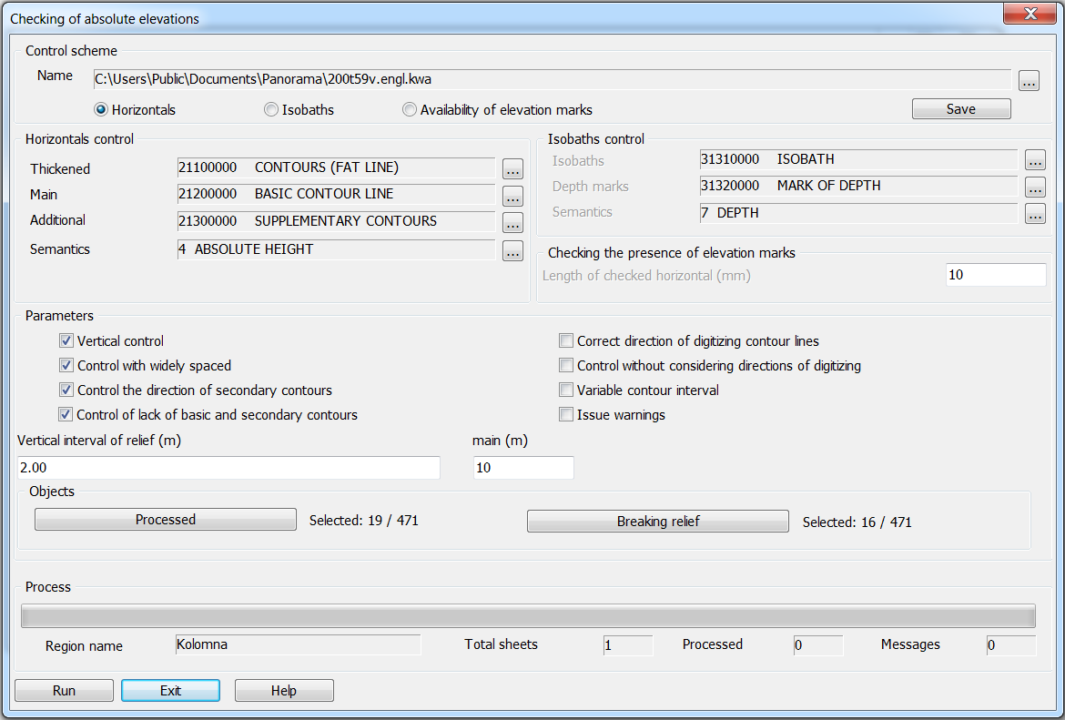
Dialog view:
Types of control: - control of horizontals; - control of isobaths; - control of elevation marks.
Contour lines control checks the elevations of thickened, main and additional contours, as well as other objects with the «absolute height» semantics. Control of isobaths checks the values of isobaths depths and marks of depths. Checking the elevation marks checks the presence of marks inside closed contour lines, as well as the planned position of the found marks relative to closed contour lines. To perform the task in different modes, it is possible to use control schemes. The types of control specified in the dialog, their parameters, as well as the composition of processed objects are saved in an XML file in the general folder of system tasks parameters «c:\Users\Public\Documents\Panorama\». The scheme file name has the «kwa» extension and is formed by the classifier name, for example - 50t05gm.kwa. The use of control schemes makes it possible to carry out a step-by-step check of relief objects in various modes. The control parameters specified in the dialog can be saved in the scheme file using the «Save» button in the «Control scheme» group. To select a previously customized scheme, use the «...» button in the «Control scheme» group. Buttons «...» in group «Horizontals control» allow to set codes of thickened, main and additional contours, and also semantics code «absolute height». Each of the given contour lines codes defines a group of classifier objects with the given code. For example, the code 21100000 defines objects of the classifier: CONTOURS THICKENED ON LAND, CONTOURS THICKENED ON ROCKS, CONTOURS THICKENED ON GLACIER. Buttons «...» in group «Isobaths control» allow to set codes of isobaths, depth marks, and also a code of semantics «depth». For the convenience of customizing control schemes, the buttons for selecting codes and semantics «...» in the groups «Horizontals control» and «Isobaths control» remain active regardless of the selected mode («Horizontals» «Isobaths») in the «Control scheme» group. In the field «Length of the checked horizontal (mm)» of the group «Checking the presence of elevation marks» is set the minimum length of the closed contour (Lmin) in millimeters of the map. This parameter is used when checking the planned position of the found mark of elevation relative to the closed contour enveloping it. If the length of the closed contour is less than Lmin, then the distance from the elevation found inside the contour to the contour itself is not checked. Otherwise (if the length of the closed contour is greater than Lmin), the distance from the mark to the closed contour enveloping it is checked. If the distance is less than 0.5 mm of the map (the mark «sticks» to the horizontal), then an error message is issued about the planned position of the elevation mark. Modes of control of relief's objects are set in the «Parameters» group. «Vertical control» - after horizontal profiling the objects of sheet, the vertical profiling is carried out. Improves the quality and reliability of results of control. «Control with widely spaced» - allows to take into account the presence of sparse contours on the map. The mode is used to reduce error messages in the presence of discharge of contours on the checked sheet. «Control the direction of secondary contours» - is used to check the direction of digitization of additional contours. If it is not specified, then additional contours are checked only in elevation. «Control without considering the directions of digitizing» - is used to reduce error messages at the non-observance of direction of digitizing contours. «Variable contour interval» - for control of absolute elevations of a topographic map with variable contour interval. «Issue warnings» - disabled by default. Disabling this mode allows you to reduce the number of program messages, which makes it easier to analyze the control results. Warnings are «Discrepancy of elevations» messages that display the same elevation values for two objects. «Vertical interval of relief (m)» - for a topographic map with a constant contour interval, it is taken from the passport of the first sheet. If absent in the passport, it is taken from the control scheme. At control of absolute elevations of a topographic map with variable elevation of section, in the field «Vertical interval of relief (m)» When checking the absolute elevations of a topographic map with a variable contour interval, in the «Vertical interval of relief (m)» field should be, for example: -150 500 10 500 2000 20 2000 8000 50, where:-150 (min) 500 (max) 10 (section), 500 (min) 2000 (max) 20 (section) etc. When checking the absolute elevations of general geographical map according to the specified values of elevations, in the field «Vertical interval of relief (m)» should be, for example: 10 20 50 100 200 500 1000 1500 2000, where 10,20,50,… are the elevations of contour lines on this sheet. When checking the isobaths of topographical or general geographical map on preset values of depths, in the field «Vertical interval of relief (m)» should be, for example: 2 5 10 20 50 100 150 200, where 2,5,10, … - are the depths values of the isobaths. The «Processed» button in the «Objects» group - to set the composition of the checked map objects. By default, all linear, areal and point objects with the «absolute height» semantics are processed. The «Breaking relief» button in the «Objects» group is used to set the composition of linear and areal objects that break the sequence of elevations (for example, areal rivers, cliffs, quarries, ravines, and others). As a result of the task working, a protocol of control messages is created for the processed sheets of the region, which can be viewed in the «Map Editor» task - the «View error» mode. The protocol line contains information about the numbers and elevations of objects that are not coordinated by codes, elevation or direction of digitization. The sign «-» (minus) at the elevation value indicates the direction of digitization «from top to bottom», the sign «+» (plus) - to the direction of digitization «from bottom to top».
|